
A REAL GRID DIP METER This started as an exercise in cleaning out some old junk boxes and tube era vintage parts that I couldn't seem to sell or give away. I tried to think of what, if anything, small receiving type tubes were better at than solid state components. Infinite impedance (or at least very, very high impeance) voltmeters (VTVMs) and the Grid Dip Meter (or Oscillator or ""GDO") came to mind. Here's how a tube based GDO turned out. CLICK HERE FOR: SCHEMATIC (Sheet 1 PDF) SCHEMATIC (Sheet2 PDF) Link to howto make pretty calibrated dial Link to 7586 Nuvistor data A description of the GDO design and some hints on how to use it follows the pictures. |
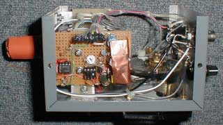

THE FINAL PRODUCT |
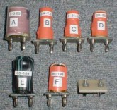
COILS COVERING 1-195 MHz |
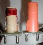
COIL CONSTRUCTION |
METER AMP AND POWER SUPPLY |
EQUIVALENT FET OSC |
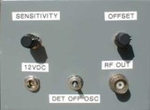
END PANEL WITH CONTROLS & PWR |
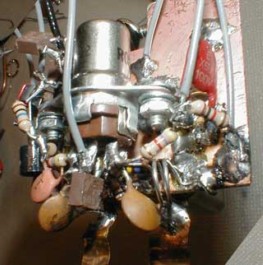
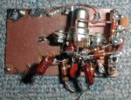
PROTOTYPE OSC BOARD |
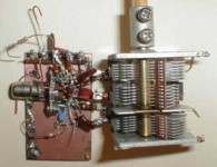
TESTING OSC+VAR CAP |
COIL ATTACHES HERE <========= AND <========= HERE |
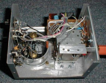
INSIDE VIEW OF GDO |
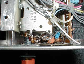
SIDE VIEW |
OSCILLATOR BOARD |
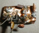
OSC WEDGED BETWEEN VARIABLE CAP AND CASE. COIL JACK ON LEFT |
A "REAL" GRID DIP METER A 'Grid Dip Meter' or "Oscillator' (GDO) is a relatively simple piece of test equipment consisting of a tunable oscillator with an exposed plug-in coil for covering a wide range of frequencies. It has a sensitive meter to measure grid current as an indication of the strength of the oscillations. Any external resonant circuit (LC, transmission line stub, « wavelength piece of wire, loop, etc.) in the magnetic field of the exposed GDO coil or capacitance coupled to it will interact with the GDO. If this external circuit is resonant near the GDO frequency it will absorb some of the GDO energy and cause the grid current meter to "dip" with the maximum dip when the two are tuned to the same frequency. The tuning capacitor for the GDO normally has a calibrated frequency scale for each coil. Other modes of operation include using the GDO for a signal generator with optional AM modulation and as a (relatively insensitive) tuned AM diode detector or signal tracer. . Due to de-tuning, loading and pulling, very loose coupling between the GDO and the external circuit are required for accurate frequency measurements. De-tuning is the shift in resonance caused by the equivalent capacitance or inductance introduced by the proximity of the two circuits. Loading is the effect on the GDO due to the energy absorbed by the external circuit. Of course loading can't be reduced to zero since it's what causes the dip we are looking for but it can also introduce a frequency error. It's adverse effects can be minimized by having a sensitive instrument able to measure small changes and keeping the two circuits as far apart as possible where the needle barely dips. Pulling is the tendency of an oscillator to try and track the resonant frequency of a second, coupled resonant circuit or external signal near the oscillator. Pulling only takes place after the GDO and the external circuit/signal have been tuned to the exact same frequency. The GDO will tend to oscillate closer to the frequency of the second circuit/signal than it would if the second circuit/signal were just moved or connected into the coupled condition without the two circuits having been on the same frequency. The tracking will continue as long as the conditions for oscillation are met (usually only a small percentage of the operating frequency) and then the GDO will "snap" to it's own normal resonant frequency (with possible de-tuning effects still present. You can sometimes detect this as a sudden jump (up or down) in the meter as either the GDO or external circuit/source is tuned. It tends to be much more pronounced in one direction (up or down) than the other. To minimize the above effects start with rather close coupling until you find the right coil and find the dip. Then increase offset (CCW) and increase gain (CW) if necessary so you can still see the dip with reduced coupling. The problem with solid state FET or bipolar transistors is that there is no real equivalent of grid current. The GDO implemented with solid state devices doesn't seem to have the sensitivity of the legendary Measurements Corp. "Megacycle Meter" which had a 955 Acorn tube in a round RF head. Also, the amplitude across a band seems more constant with a tube oscillator making it easier to sweep the whole range of one coil without having to readjust the sensitivity. I ran across some old Tektronix scope plug-ins which used tiny 7586 "Nuvistor" tubes and salvaged some tubes and a couple sockets. Many of the tubes had low or no emission but two were in good shape. The oscillator circuit from the old Measurements unit was roughly followed in this design. A rather low 30V plate supply was sufficient for operation up to almost 200MHz with less than 10V being sufficient on some lower frequencies.. Some other candidate tubes might be other Nuvistors or triodes like the 6C4 or the UHF tuner 6AF4 (7-pin miniature). There are a number of subminiature pencil sized tubes still around, too. Other than the oscillator which requires a two-section variable capacitor there is just the power supply and a DC op-amp meter amplifier. Although the cheap LM358's work OK down to the negative rail (ground) adding the optional negative supply shown in the schematic would prevent the occasional annoying latch-ups. The oscillator is fairly stable over most of its range falling off at the very low end and with a few dips above 50MHz. These are likely due to lead lengths, parasitic resonances, or whatever. They weren't bad enough to track down. I just guessed at the coil in the cathode of the tube (without even looking inside the Megacycle Meter) with the intention of trying to figure it out later. Well, it's so crammed in tight and there doesn't seem to be anything wrong enough to be worth chasing after. May be related to the >50MHz dips. The first op-amp is used to invert the negative grid current into a positive voltage the op-amps can deal with. There is a DC offset as the grid current develops almost -1V across the 2.2K resistor on the lower bands with the dips being 50mV or less depending on coupling. The offset allows the gain to be increased so the meter reads 0 at -900mV and full scale at -800mV for of a dip of « scale which is easier to spot. Increasing the gain this way also magnifies the variation in oscillator output/activity across the band so you may not be able to keep the meter on-scale without some readjustment. The second op-amp is just a variable gain non-inverting amp. The diodes limit the output to reduce banging the meter needle if you adjust the meter FS just below the compression point of 1 to 1.5V. The coils have odd ranges because I had it all working with a small plastic AM/FM clock radio variable cap which then died. Moving to a different cap shifted everything but I was too lazy to redo all the coils. Coil F needed adjusting and coil E was added to fill in a gap that appeared. As with anything you expect to work smoothly at higher frequencies, keep all the leads in the oscillator as short as possible. In mine the oscillator board is jammed in the 5/8" or so distance between the case and the variable capacitor which is the length the banana jacks protrude inside the case. Each coil spans almost but not quite a 3:1 frequency range but you should allow a little overlap between bands. (Frange is approx = sqrt( (Cmax + Cstray) / (Cmin + Cstray) ) and varies with capacitor range. C3a, C3b is a dual 4.5 - 130pF variable (actually there is a third, unused section). Note that the frame is not grounded so you will need an insulated shaft or knob to keep your hand from affecting the tuning. The original used 110pF sections but other, larger values would also work. I tried up to a dual 410pF out of curiosity and it worked OK and with a little wider frequency coverage range per coil. Be sure to remove any built in trimmer capacitors to reduce stray capacitance. You could add a 2pF or so trimmer or "gimmick" to compensate if you should ever have to change the tube. Use ¬" wide thin copper foil if you can't solder the banana jacks directly to the capacitor. Actually, the foil isn't a bad idea to allow some flexing between the two when you insert and remove coils. SOME COMMON GDO USES: 1. Tuning stubs, traps or filters (individual elements) 2. Tuning or finding the resonance of any LC circuit 3. Looking for spurious transmitter oscillations (careful!) 4. Checking dipole or beam element resonance 5. Measuring inductance (connect L in place of regular coil easier with a capacitance calibration scale) 6. Initial tuning up a piece of gear with power off 7. Checking the length of a piece of transmission line 8. Signal generator (with harmonics on RF Out) 9. Checking if an amplifier/multiplier stage is tuned to or has output on right frequency CIRCUIT / CONSTRUCTION NOTES This GDO oscillator circuit is based on an old Measurements Corp. Model 59 "Megacycle Meter" - the best grid dip meter that I've ever seen or used. It had a 955 acorn tube. BAND COILS FREQ L Form A 1.3 - 2.8 288uH 3/4" 1120 PVC B 2.8 - 8.3 47uH 1/2" CPVC C 8.3 - 22.6 5.3uH 1/2" CPVC D 22.6 - 62 0.6uH 1/2" CPVC E 62 - 179 Hairpin #12 13/16" W x 2-1/8" L Coil bases salvaged from old Tek scope parts w/ bananna plugs on 3/4" centers R1 and R2 in the original were 13.6K each consisting of two 6.8K resistors in series. The schematic shows lots of 110K resistors just because I had them - 100K OK. Q4 HV Control can be used to adjust the plate voltage or switch it off for diode detector mode. |
GRID DIP METER SETUP INSTRUCTIONS SENSITIVITY (meter amp gain) full CCW. OFFSET full CW. RF OUT 1VPP to counter. Use OSC for GDIP, DET for detector (not very sensitive). GDIP: Increase Sens. CW to get _ scale ind. For max sens. turn Off. CCW to ¬ scale and incr. Sens. CW. If Off. set too low (< 1 on meter) Op-Amp may latch up. For accurate dip reduce coupling once found. |
INSTRUCTION SHEET (ATTACH TO SIDE PANEL) |